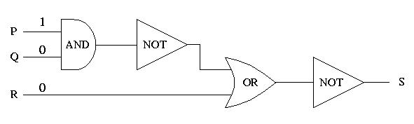
1. The inputs to the circuit are given in the following diagram:
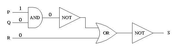
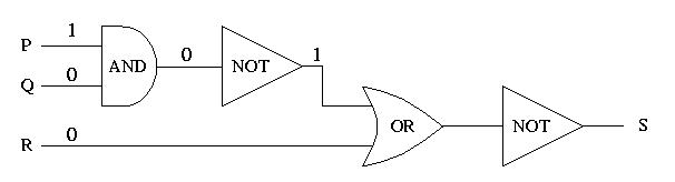
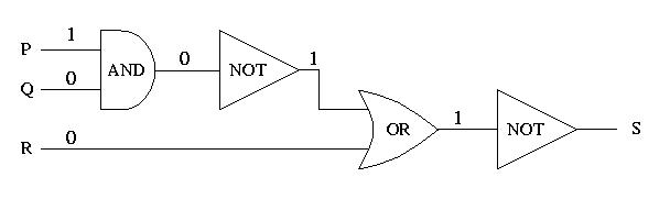
Progress through the circuit from left to right, determining the output of each logic gate.
Back to Section 1.4 Full solution